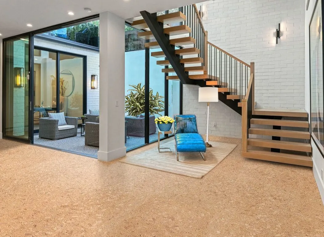
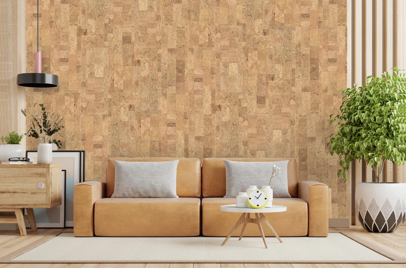
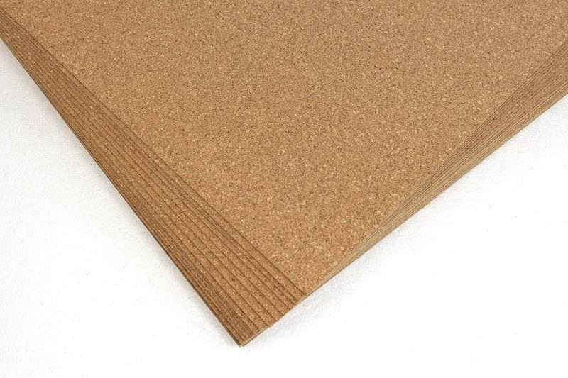
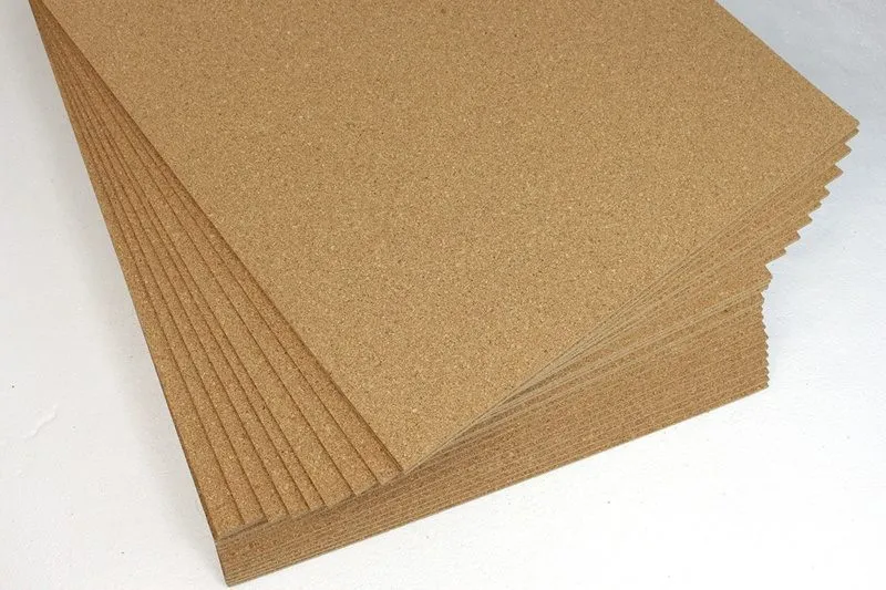
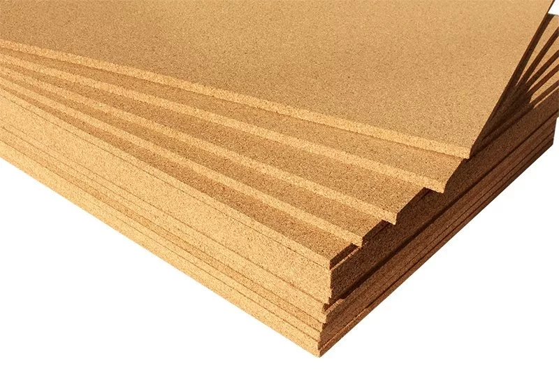

Installation of Forna Cork Floating Floors
The unique UNICLIC® mechanism allows Frona floating flooring to be placed quickly and efficiently. The pieces are contoured to fit perfectly all around and are mechanically secured together, allowing them to be connected without adhesive. This floor has convincing features such as exceptionally durable, non-slip, dirt-repellent, and antistatic. Please note that Traditional Cork Floorings (especially with stain) require a Top Layer Polyurethane. Chipboard or wooden floors must be sanded if necessary. All flooring must be vibration-free, and if necessary, it needs to be re-screwed. Unless otherwise specified, Forna floating floors are not suited for wet spaces.
Preparing the subfloor
Forna Floating flooring is installed in the same way as a floating floor. In line with DIN 18365 “Floor covering work,” the substrate must be clean, permanently dry, level, and tension and compression resistant. Paint droplets, plaster residues, and other slight, protruding unevenness must be eliminated.
The substrate’s evenness must meet the requirements of DIN 18202 “Evenness tolerances” Table 3 / Line 4. The maximum height tolerance of 3/32 inch per 3.28 feet (3 mm per metre) must not exceed. Unevenness must be filled in with the appropriate filling compound. It is not possible to install on any carpeting. The use of full-surface glueing to the substrate is not recommended. Moisture measurement of the substrate must be performed and documented before installation.
Pre-Installation
Tempering and storage
For acclimatization, store the closed Forna Flooring packages lying flat in the installation room for at least 24 hours at 59F – 77F (15 – 25 °C) and relative humidity of 40 – 60%.
Check
Before installation, the planks must be thoroughly inspected in daylight for transportation damage and any material faults. Minorly damaged planks can be treated in places where cutting is already required. Slight colour and structure variations are caused by the material and add to the natural character. Check that the subfloor and building conditions comply with the instructions. Do not begin the installation if the material or the building conditions do not meet the standards. There are no claims for processed material replacement; processed and installed items are accepted goods.
PE foil / moisture barrier / sliding layer
All mineral substrates must have a moisture barrier with an Sd value of less than 100 m (e.g. 0.2 mm PE film). This should be taped at the joints and should overlap by about 7.87 inches (20 cm). The film should be dragged up about 0.78 inches to 1.18 inches (2 to 3 cm) on the walls. To enhance floating of the floor – on a sliding layer – it is advisable to use PE foil on any subfloor.
Mat for isolation
Forna prefabricated flooring comes with a laminated cork or Green Sound impact sound isolation that eliminates the need for additional impact sound isolation. If you decide to enhance further, the isolation mat you choose must have a minimum CS value of 200 kPa (pressure resistance at defined compression strength).
Room size limit
For Swiss Design Cork: Without additional expansion joints, the maximum permitted area is 49 feet x 39 feet (15 m × 12 m).
For all other floating floors: Without additional expansion joints, the maximum permitted area is 25 feet x 25 feet (7.6 m × 7.6 m).
Joints
Larger portions are divided into smaller parts by joints, and smaller areas are separated from other components by joints. In cooperation with the commissioner, follow the screed layer’s joint strategy and establish them. Movement joints defined in the building’s substrate (for example, the screed of separate rooms touching one other) must be taken over in a consistent manner.
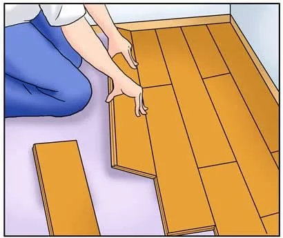
Installation
To get an even installation pattern, it is not necessary to open the packages until you are ready to install. When installing, open and and combine planks from different packages. The floor is laid out as if it were a floating floor. The click connection is the only one that is mechanically locked. The planks must not be spot glued, fastened, screwed, or secured to the flooring by other heavy things. Movement joints at the level of the building components must be used to divide room portions that are interrupted by pillars, entrances, or other obstacles.
Additional expansion joints are required for asymmetrical area cross-sections/angled rooms longer than 32.80 feet or 10 m in one direction. Kitchen blocks, cooking islands, wood and night storage heaters, and other heavy objects that can prevent the floor from floating must be entirely decoupled from the floor (either installed before laying the floor or established expansion joints around the objects).
Additional bond the tongue and groove joint on the front and long sides using D3 wood glue in rooms where partial standing damp is expected or heavy objects are part of the furnishings (e.g., closet, kitchen).The laying should be done lengthwise to the light’s incidence. Forna Floating Floors are not suited as a self-supporting floor on joist ceilings.
Measure the available space. If the last row isn’t at least 1.96 inches (5 cm) broad, cut the first row, so the first and last rows are around the same width. At least 0.39 inches (10 mm) must be left between the wall and other components (for larger rooms, at least 0.4 inches per 3.28 feet or 1 mm per metre of room width). The innovative UNICLIC® Click System offers two installation options from the second row onwards.

Example of an Angle to Angle Installation
Variation 1 of the installation “Angle to Angle”
First Row – Begin laying in the room’s right corner.
The tongue side of the first plank should face the wall. Use spacer wedges to align it perfectly. Lever the second plank into the first plank’s front groove with its front tongue in precise extension. Start laying the second row using the last piece of the first row’s last plank after the first row has been perfectly aligned with a setting lath or string. The cross or end joints should be offset by at least 20 cm, but ideally by 40 cm.
Second Row – Using a tapping block and hammer, position the first plank of the second row at a bit of angle on the long side (max. 10° / 0.78 – 1.18 inches or 2-3 cm) and click it into the plank of the first row. Then, slightly elevate the second plank and the plank next to it (both already clicked in) and click them lengthwise (max. 10° / 0.78 – 1.18 inches or 2-3 cm). You can ensure an effective joint closure by lightly striking the longitudinal side of the plank and the end of the plank with a tapping block (minimum length 7.87 inches or 20 cm) and a hammer – never use excessive pressure. Place the following planks in a straight line with the first.
Variation 2 of the installation “Angle Snap”
First Row – Begin by laying in the room’s right corner. The tongue side of the first plank should face the wall. Use spacer wedges to align it perfectly. Place the second board in front of the first and use a tapping block and hammer to tap them together. Ensure that the planks are in a straight line. Start laying the second row with the last piece of the first row’s last plank after the first row has been perfectly aligned with lath or string. The cross or end joints should be offset by at least 7.87 inches or 20 cm, but ideally by 15.74 inches or 40 cm.
Second Row – Using a tapping block and hammer, click the first plank of the second row into the plank of the first row at a modest angle on the longitudinal side (max. 10° / 0.78 – 1.18 inches or 2-3 cm). The panels are clicked into position on the front side by tapping softly with the tapping block. The tapping block (at least 20 cm long) should always be placed on the tongue or the lower groove cheek, never on the “good edge.” Place the following planks in a straight line with the first. After the installation is complete, the spacer wedges must be removed.

Example of an Angle Snap Installation
Pipes for heating and door stoppers
Maintain a minimum distance of 7.87 inches or 10 mm around the obstacle. Cut a wedge-shaped piece towards the edge, starting at the hole. Replace the cut portion with adhesive tape and lay the plank down. Specialty stores have a variety of cover caps and rosettes. Do not screw the doorstop into the subfloor through the floating floor. The floor will not float as a result of this.
Frames for doors
Place a loose plank against the door frame with the top facing down, cut it off, and shorten it as needed so the elements may be laid floating underneath. Ensure the boards have enough flexibility, especially in this location – the door frames should not be firmly planted on the floor.
Accessories
The skirting profiles should be attached to the wall rather than the floor.
Furthermore, the installation of the floor profile must not obstruct the floating of the floor.
Heating beneath the flooring
Follow the underfloor heating manufacturer’s/instructions installer’s as well as any applicable requirements. The surface temperature must not surpass 84.2F or 29°C after the heating system has been turned on. It is recommended that you adopt a heating protocol approved by the screed manufacturer, as the recommended heating and unheating phases are specified there. If the specifications listed above are followed, and the system is equipped with a control unit, installation on electric underfloor heating systems is possible. Furthermore, the click connection must be bonded in a few places.